
Артикул: RX7621
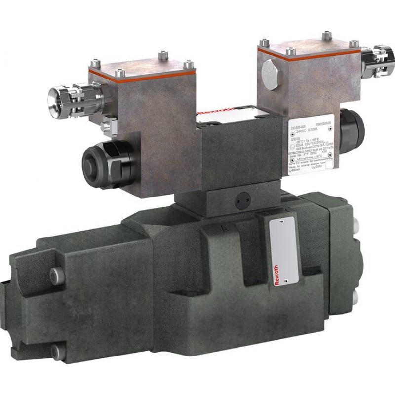
Proportional directional valves, pilot operated, without electrical position feedback 4WRZ ...XE
Доступно к заказу
Цена по запросу
И выбери подходящего.
Description
- Size 10, 16, 25, 32
- Component series 7X
- Maximum operating pressure 350 bar
- Maximum flow 1600 l/min
- Area of application in accordance with the Explosion Protection Directive 2014/34/EU: II 2G; II 2D
- Type of protection valve:
– Ex h IIC T4 Gb X according to EN 80079-36
– Ex h IIIC T115°C Db X according to EN 80079-36 - Type of protection, solenoid coil:
– Ex eb mb IIC T4 Gb according to EN 60079-7 / EN 60079-18
– Ex tb IIIC T115°C Db according to EN 60079-31 - Solenoid coil certified according to IECEx
Features
- 4/2 or 4/3 directional design
- For intended use in potentially explosive atmosphere
- For the control of flow direction and size
- For subplate mounting
- Porting pattern according to ISO 4401
- Spring-centered control spool
- Actuation by means of the pilot control valve (3-way pressure reducing valve)
- Solenoid coil is rotatable by 90°
- Electrical connection as individual connection with cable gland
Product description
Valves of the type 4WRZ... are pilot-operated proportional directional valves that are actuated by means of proportional solenoids. Their function is to control the flow direction and size.
The proportional solenoids are controlled by external control electronics.
Set-up
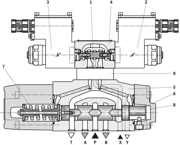
The valve basically consists of:
- Pilot control valve (4) with proportional solenoids (2 and 3)
- Pressure reducing valve (9)
- Main valve (5) with main control spool (6) and centering spring (7)
Function
- With de-energized solenoids (2 and 3), the main control spool (6) is held in central position by means of a centering spring (7)
- The main control spool (6) is controlled by the pilot control valve (4); the main control spool is proportionally moved, e.g. by actuating solenoid "b" (3)
- The control spool (1) is moved to the right, pilot oil enters the pressure chamber (8) via the pilot control valve (4) and deflects the main control spool (6) proportionally to the electric input signal to the left
- Connection from P → A and B → T via orifice-type cross-sections with progressive flow characteristic
- Pilot oil supply to the pilot control valve internally via port P or externally via port X
- Switching off the solenoid (3)
- The control spool (1) and main control spool (6) are moved back into the central position
- Flow depending on spool position from P → A and B → T or P → B and A → T.
Notice:
With pilot control valves of the version "3DREP 6 C", only one solenoid may be actuated at a time.
Type 4WRZ...-7X./...
Type code
| 01 | 02 | 03 | 04 | 05 | 06 | 07 | 08 | 09 | 10 | 11 | 12 | 13 | |||
| 4WR | Z | ‒ | 7X | / | 6E | G24 | XE | J | / | D3 |
| 01 | Proportional directional valve | 4WR |
| 02 | Electro-hydraulic actuation | Z |
| 03 | Size 10 | 10 |
| Size 16 | 16 | |
| Size 25 | 25 | |
| Size 32 | 32 | |
| 04 | Symbols; for the possible version, see "Symbols/Circuit diagrams" | |
| Nominal flow | ||
| 05 | Size 10 | |
| 25 l/min | 25 | |
| 50 l/min | 50 | |
| 85 l/min | 85 | |
| Size 16 | ||
| 125 l/min | 125 | |
| 180 l/min | 180 | |
| Size 25 | ||
| 220 l/min | 220 | |
| 325 l/min | 325 | |
| Size 32 | ||
| 360 l/min | 360 | |
| 520 l/min | 520 | |
| 06 | Component series 70 … 79 (70 … 79: unchanged installation and connection dimensions) | 7X |
| 07 | Proportional solenoid | 6E |
| Supply voltage of the control electronics | ||
| 08 | Direct voltage 24 V | G24 |
| Explosion protection | ||
| 09 | “Increased safety”, for details, please refer to the "information on explosion protection" | XE |
| Corrosion resistance (outside) | ||
| 10 | Increased corrosion protection, galvanized | J |
| Pilot oil supply and return | ||
| 11 | External pilot oil supply, external pilot oil return | no code |
| Internal pilot oil supply, external pilot oil return | E | |
| Pilot oil supply internal, pilot oil return internal | ET | |
| External pilot oil supply, internal pilot oil return | T | |
| 12 | With pressure reducing valve (fixedly set) | D3 |
| Seal material (observe compatibility of seals with hydraulic fluid used, see "Technical data") | ||
| 13 | NBR seals | M |
| FKM seals | V | |
Technical data
general
| Size | 10 | 16 | 25 | 32 | ||
| Weight | Valve with one solenoid | kg | 8.5 | 12.5 | 18.5 | 44.5 |
| Valve with two solenoids, spring-centered | kg | 10 | 14 | 20 | 46 | |
| Installation position | any, preferably horizontal | |||||
| Ambient temperature range | °C | -20 … +60 | ||||
| Storage temperature range | °C | +5 … +40 | ||||
| Maximum storage time | yrs | 1 | ||||
| Surface protection | Galvanized | |||||
hydraulic
| Size | 10 | 16 | 25 | 32 | |||
| Maximum operating pressure | Ports A, B, P | External pilot oil supply | bar | 350 | |||
| Internal pilot oil supply | bar | 315 | |||||
| Port T | External pilot oil supply | bar | 315 | 250 | |||
| Internal pilot oil supply | bar | 30 | |||||
| Port X | bar | 315 | |||||
| Port Y | bar | 30 | |||||
| Hydraulic fluid | see table "Hydraulic fluid" | ||||||
| Hydraulic fluid temperature range | NBR seals | °C | -20 … +80 | ||||
| FKM seals | °C | -15 … +80 | |||||
| Viscosity range | Maximum admissible | mm²/s | 20 … 380 | ||||
| Recommended | mm²/s | 30 … 46 | |||||
| Maximum admissible degree of contamination of the hydraulic fluid, cleanliness class according to ISO 4406 (c) 1) | Pilot control valve | Class 17/15/12 | |||||
| Main valve | Class 18/16/13 | ||||||
| Maximum flow | Main valve | l/min | 170 | 460 | 870 | 1600 | |
| Minimum pilot pressure | Pilot control valve | bar | 30 | ||||
| Pilot flow | Port X and Y | Eingangssignal 0 → 100% | l/min | 3.5 | 5.5 | 7 | 15.9 |
| Pilot volume | Schaltvorgang 0 → 100% | cm³ | 1.7 | 4.6 | 10 | 26.5 | |
| Hysteresis | % | ≤ 6 | |||||
| 1) | The cleanliness classes specified for the components must be adhered to in hydraulic systems. Effective filtration prevents faults and simultaneously increases the life cycle of the components. |
| Hydraulic fluid | Classification | Suitable sealing materials | Standards | Data sheet | |
| Mineral oils | HL, HLP, HLPD, HVLP, HVLPD | NBR, FKM | DIN 51524 | 90220 | |
| Bio-degradable | Insoluble in water | HETG | FKM | ISO 15380 | 90221 |
| HEES | FKM | ||||
| Soluble in water | HEPG | FKM | ISO 15380 | ||
| Flame-resistant | Water-free | HFDU (glycol base) | FKM | ISO 12922 | 90222 |
| HFDU (ester base) | FKM | ||||
| HFDR | FKM | ||||
| Containing water | HFC (Fuchs: Hydrotherm 46M, Renosafe 500; | NBR | ISO 12922 | 90223 | |
| Important information on hydraulic fluids:
| |||||
electrical
| Voltage type | Direct current or pulse-width modulated signal with a pulse voltage ≤ 28 V and a frequency ≥ 160 Hz up to max. 500 Hz | ||
| Type of signal | analog | ||
| Maximum solenoid current | A | 1.03 | |
| Actuated time | % | 100 | |
Information on explosion protection
| Application according to Explosion Protection Directive 2014/34/EU | II 2G | II 2D |
| Type of protection of the valve according to EN 80079-36 1) | Ex h IIC T4 Gb X | Ex h IIIC T115°C Db X |
| Type of protection, solenoid coil according to EN 60079-7 / EN 60079-18 / EN 60079-31 | Ex eb mb IIC T4 Gb | Ex tb IIIC T115°C Db |
| Maximum surface temperature 2) | 115 °C | |
| Temperature class | T4 | - |
| Type examination certificate solenoid coil | BVS 20 ATEX E 009 X | |
| "IECEx Certificate of Conformity" solenoid coil | IECEx BVS 2007 X | |
| 1) | Ex h: structural safety c according to EN 80079-37. |
| 2) | Surface temperature > 50 °C, provide contact protection. |
Special application conditions for a safe application
- Connection lines must be passed in a strain-relieved way. The first mounting point must be within 150 mm of the cable and line entry.
- In case of valves with two solenoids, maximally one of the solenoids may be energized at a time.
- Only direct voltage or a pulse-width modulated signal with a pulse voltage ≤28 V and frequency ≥160 Hz … up to max. 500 Hz may be used.
- The maximum temperature of the surface of the valve jacket is 115 °C. This has to be considered when selecting the connection cable and/or contact of the connection cable with the surface of the jacket is to be prevented.
Control electronics
| Valve amplifier for proportional valves without electrical position feedback; maximum current limitation 1 A | VT-MSPA2-2X/A5/1A0/000 (data sheet 30232-01) |
| Module for monitoring and limiting the solenoid currents with proportional valves | VT-MUXA2-2-1X/V0/1A (data sheet 30290) |
| A monitoring circuit is to be provided for the monitoring of the solenoid current. We recommend operating the valves with the assemblies described herein. The valve amplifier and the monitoring module may only be installed outside the potentially explosive atmosphere. |
(For applications outside these values, please consult us!)
Diagrams/characteristic curves
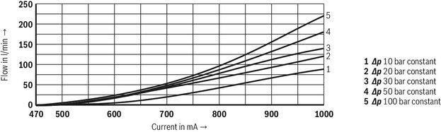
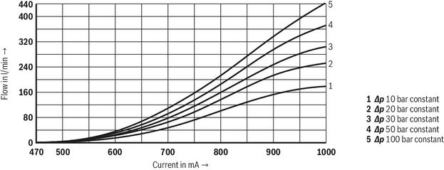
(measured with symbol E, W6-, EA, W6A, HLP46, ϑOil = 40 ±5 °C)
Size 10
Rated flow 25 l/min
(P → A; B → T or P → B; A → T)
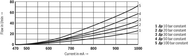
Rated flow 50 l/min
(P → A; B → T or P → B; A → T)
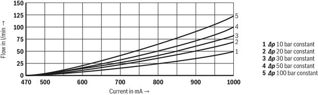
Rated flow 85 l/min
(P → A; B → T or P → B; A → T)
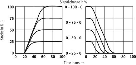
Transition function with stepped electric input signals
(measured with pilot pressure pSt = 50 bar)
Size 16
Rated flow 125 l/min
(P → A; B → T or P → B; A → T)
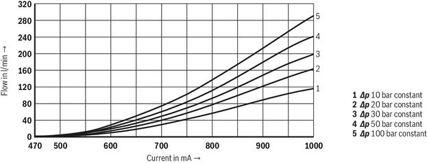
Rated flow 180 l/min
(P → A; B → T or P → B; A → T)
Transition function with stepped electric input signals
(measured with pilot pressure pSt = 50 bar)
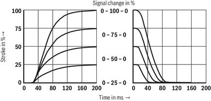
Size 25
Rated flow 220 l/min
(P → A; B → T or P → B; A → T)
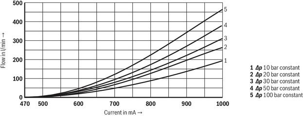
Rated flow 325 l/min
(P → A; B → T or P → B; A → T)
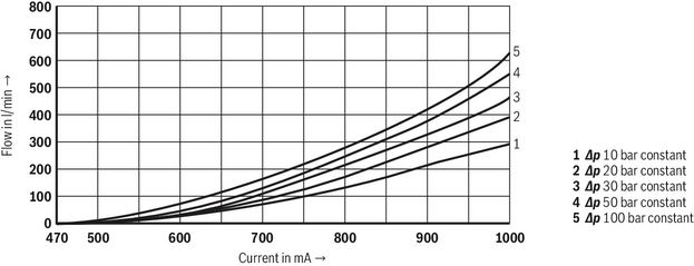
Transition function with stepped electric input signals
(measured with pilot pressure pSt = 50 bar)
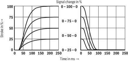
Size 32
Rated flow 360 l/min
(P → A; B → T or P → B; A → T)
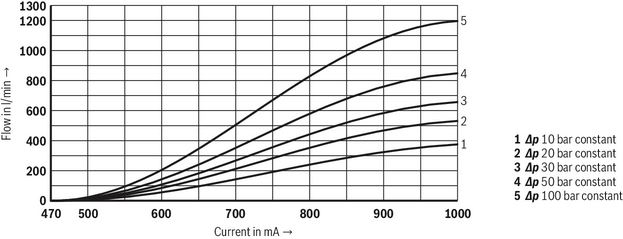
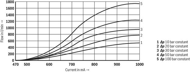
Rated flow 520 l/min
(P → A; B → T or P → B; A → T)
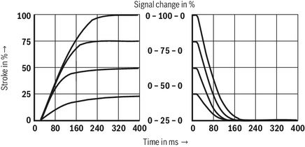
Transition function with stepped electric input signals
(measured with pilot pressure pSt = 50 bar)
| Δp = pP – pL – pT (according to DIN 24311) | |
| Δp | Valve pressure differential |
| pP | Inlet pressure |
| pL | Load pressure |
| pT | Return flow pressure |
(measured with HLP46, ϑÖl = 40 ±5 °C)
Symbols/Circuit diagrams
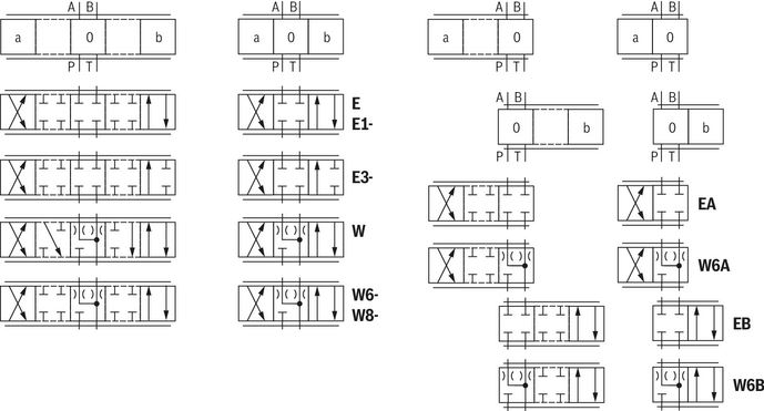
| With symbols E1- and W8-, the following applies: | |
| P → A: qvmax | B → T: qv/2 |
| P → B: qv/2 | A → T: qvmax |
| With symbols E3- and W9-, the following applies: | |
| P → A: qvmax | B → T: blocked |
| P → B: qv/2 | A → T: qvmax |
| (Differential circuit, piston top at port A) |
Notices:
- With symbols W, W6-, W8-, W9-, W6A and W6B, there is - in the “0” spool position - a connection from A → T and from B → T with less than 2% of the relevant nominal cross-section.
- Representation according to ISO 1219-1.
- Hydraulic interim positions are shown by dashes.
Pilot oil supply
| 3 spool positions | 2 spool positions (Version ".A)" |
|
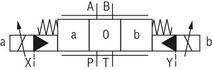 | 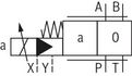 | "4WRZ" External pilot oil supply, external pilot oil return The pilot oil is supplied from a separate control circuit (external). The pilot oil return is not directed into channel T of the main valve, but is separately directed to the tank via port Y (external). |
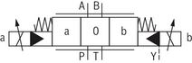 | 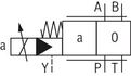 | "4WRZ…E" Internal pilot oil supply, external pilot oil return The pilot oil supply is implemented from channel P of the main valve (internally). The pilot oil return is not directed into channel T of the main valve, but is separately directed to the tank via port Y (external). |
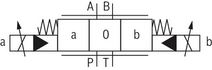 | 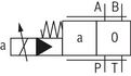 | "4WRZ…ET" Pilot oil supply internal, pilot oil return internal The pilot oil supply is implemented from channel P of the main valve (internally). The pilot oil is directly returned to channel T of the main valve (internally). |
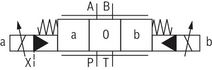 | 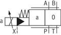 | "4WRZ…T" External pilot oil supply, internal pilot oil return The pilot oil is supplied from a separate control circuit (external). The pilot oil is directly returned to channel T of the main valve (internally). |
Electrical connection
The type-examination tested solenoid coil of the valve is equipped with a terminal box, a type-examination tested cable entry and a type-examination tested blind plug.
The connection is polarity-independent.
Notice:
When establishing the electrical connection, the protective grounding conductor (PE) must be connected correctly.
Suppressor diode 47 V, 1.5 kW
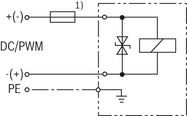
| 1) | Recommended pre-fusecharacteristics: medium time-lag according to DIN 41571; 1.25 A |
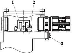
Properties of the connection terminals and mounting elements
| Position | Function | Connectable line cross-section |
| 1 | Operating voltage connection | Single-wire 0.75 … 2.5 mm2 Finely stranded,0.75 … 1.5 mm2 |
| 2 | Connection for protective earthing conductor | Single-wire 2.5 mm2 max. Finely stranded, 1.5 mm2 max. |
| 3 | Connection for potential equalization conductor | single-wire max. 6 mm2 Finely stranded, max. 4 mm2 |
Connection line
| Line type | Non-armored and non-shielded connection lines | |
| Temperature range | °C | ≤ -20 … ≥ +110 |
| Line diameter | mm | 7 ... 10.5 |
Notice:
Only use finely stranded conductors if they have pressed-on wire end ferrules.
Over-current fuse and switch-off voltage peaks
| Voltage data in the valve type code | Nominal voltage solenoid coil | Rated current Solenoid coil | Rated current for external miniature fuse: Medium time-lag (M) according to DIN 41571 and EN/IEC 60127 | Rated voltage of external miniature fuse: Medium time-lag (M) according to DIN 41571 and EN/IEC 60127 | Maximum voltage value when switching off | Interference protection circuit |
| G24 | 24 VDC | 1,03 A | 1,25 A | 250 V | -70 V | Suppressor diode bi-directional |
Notices:
Corresponding to the rated current, a fuse according to DIN 41571 and EN/IEC 60127 has to be connected upstream of every valve solenoid (max. 3 x Irated).
The shut-off threshold of the fuse has to match the prospective short-circuit current of the supply source.
The short-circuit current of the supply source to be expected may amount to a maximum of 1500 A.
This fuse may only be installed outside the potentially explosive atmosphere or must be of an explosion-proof design.
When inductivities are switched off, voltage peaks result which may cause faults in the connected control electronics. For this reason, the solenoid coil comprise an interference protection circuit which dampens this voltage peak to the voltage value shown in the table.
Dimensions
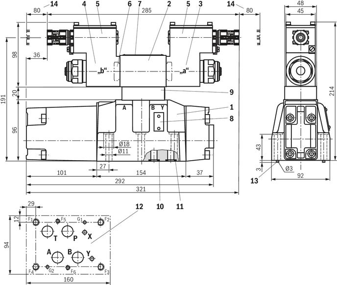
Size 10
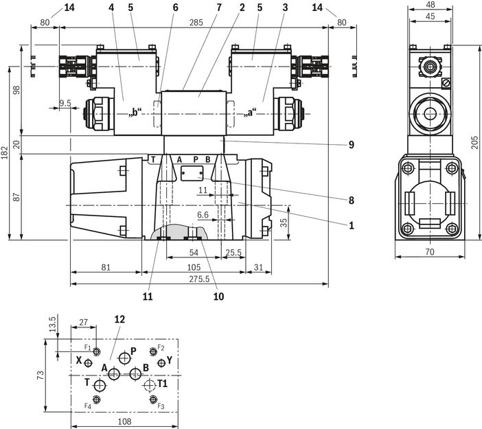
Dimensions in mm
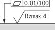 Required surface quality of the valve contact surface |
| 1 | Main valve |
| 2 | Pilot control valve |
| 3 | Proportional solenoid "a" |
| 4 | Proportional solenoid "b" |
| 5 | Terminal box |
| 6 | Plug screw for valve with one solenoid |
| 7 | Name plate pilot control valve |
| 8 | Name plate main valve |
| 9 | Pressure reducing valve (always available) |
| 10 | Identical seal rings for ports P, A, B, T and T1 |
| 11 | Identical seal rings for ports X and Y |
| 12 | Machined valve contact surface; Porting pattern according to ISO 4401-05-05-0-05 (ports X and Y as required, T1 is available at the valve and can optionally be provided) |
| 14 | Space required to remove the solenoid coil |
Notice:
The dimensions are nominal dimensions which are subject to tolerances.
Valve mounting screws (separate order)
| Size | Quantity | Hexagon socket head cap screws | Material number |
| 10 | 4 | ISO 4762 - M6 x 45 - 10.9 (Friction coefficient μtotal = 0.09 … 0.14) Tightening torque MA = 13.5 Nm ±10 % | R913043777 |
| Only use valve mounting screws with the listed thread diameters and strength properties. Observe the screw-in depth. |
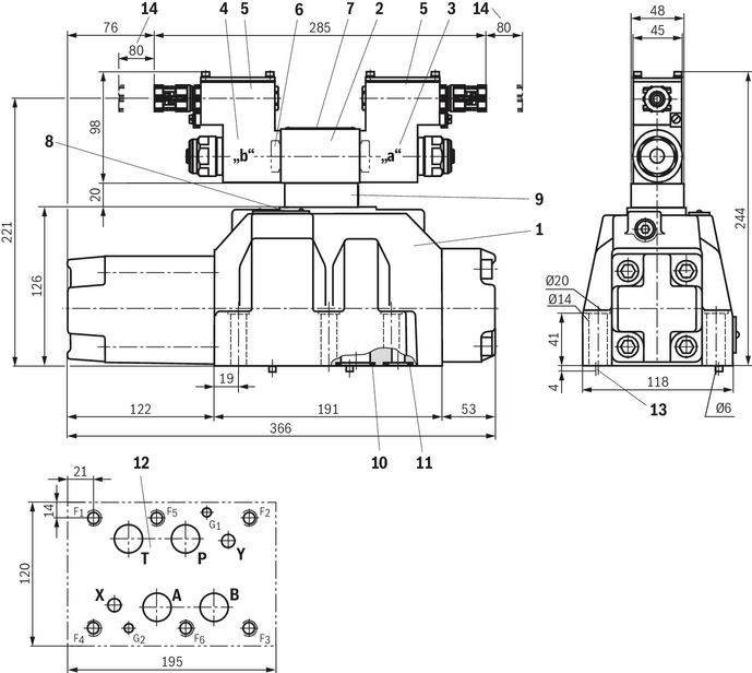
Size 16
Dimensions in mm
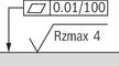 Required surface quality of the valve contact surface |
| 1 | Main valve |
| 2 | Pilot control valve |
| 3 | Proportional solenoid "a" |
| 4 | Proportional solenoid "b" |
| 5 | Terminal box |
| 6 | Plug screw for valve with one solenoid |
| 7 | Name plate pilot control valve |
| 8 | Name plate main valve |
| 9 | Pressure reducing valve (always available) |
| 10 | Identical seal rings for ports A, B, P, T |
| 11 | Identical seal rings for ports X and Y |
| 12 | Machined valve contact surface; Porting pattern according to ISO 4401-07-07-0-05 (ports X and Y as required) |
| 13 | Locating pin |
| 14 | Space required to remove the solenoid coil |
Notice:
The dimensions are nominal dimensions which are subject to tolerances.
Valve mounting screws (separate order)
| Size | Quantity | Hexagon socket head cap screws | Material number |
| 16 | 4 | ISO 4762 - M10 x 60 - 10.9 (Friction coefficient μtotal = 0.09 … 0.14) Tightening torque MA = 58 Nm ±20 % | R913014770 |
| 2 | ISO 4762 - M6 x 60 - 10.9 (Friction coefficient μtotal = 0.09 … 0.14) Tightening torque MA = 12.5 Nm ±10 % | R913043410 |
| Only use valve mounting screws with the listed thread diameters and strength properties. Observe the screw-in depth. |
Size 25
Dimensions in mm
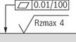 Required surface quality of the valve contact surface |
| 1 | Main valve |
| 2 | Pilot control valve |
| 3 | Proportional solenoid "a" |
| 4 | Proportional solenoid "b" |
| 5 | Terminal box |
| 6 | Plug screw for valve with one solenoid |
| 7 | Name plate pilot control valve |
| 8 | Name plate main valve |
| 9 | Pressure reducing valve (always available) |
| 10 | Identical seal rings for ports A, B, P, T |
| 11 | Identical seal rings for ports X and Y |
| 12 | Machined valve contact surface; Porting pattern according to ISO 4401-08-08-0-05 (ports X and Y as required) |
| 13 | Locating pin |
| 14 | Space required to remove the solenoid coil |
Notice:
The dimensions are nominal dimensions which are subject to tolerances.
Valve mounting screws (separate order)
| Size | Quantity | Hexagon socket head cap screws | Material number |
| 25 | 6 | ISO 4762 - M12 x 60 - 10.9 (Friction coefficient μtotal = 0.09 … 0.14) Tightening torque MA = 100 Nm ±10 % | R913015613 |
| Only use valve mounting screws with the listed thread diameters and strength properties. Observe the screw-in depth. |
Size 32
Dimensions in mm
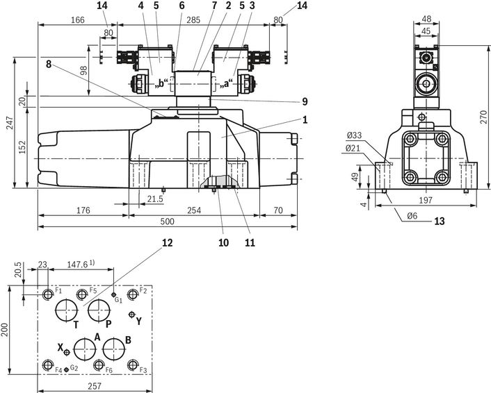
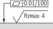 Required surface quality of the valve contact surface |
| 1 | Main valve |
| 2 | Pilot control valve |
| 3 | Proportional solenoid "a" |
| 4 | Proportional solenoid "b" |
| 5 | Terminal box |
| 6 | Plug screw for valve with one solenoid |
| 7 | Name plate pilot control valve |
| 8 | Name plate main valve |
| 9 | Pressure reducing valve (always available) |
| 10 | Identical seal rings for ports A, B, P, T |
| 11 | Identical seal rings for ports X and Y |
| 12 | Machined valve contact surface; Porting pattern according to ISO 4401-10-09-0-05 (Ports X and Y as required) |
| 13 | Locating pin |
| 14 | Space required to remove the solenoid coil |
Notice:
The dimensions are nominal dimensions which are subject to tolerances.
Valve mounting screws (separate order)
| Size | Quantity | Hexagon socket head cap screws | Material number |
| 32 | 6 | ISO 4762 - M20 x 80 - 10.9 (Friction coefficient μtotal = 0.09 … 0.14) Tightening torque MA = 340 Nm ±10 % | R913008472 |
| Only use valve mounting screws with the listed thread diameters and strength properties. Observe the screw-in depth. |
Subplates (separate order) with porting pattern according to ISO 4401, see data sheet 45100.
Notice:
Subplates are no components in the sense of directive 2014/34/EU and can be used after the manufacturer of the overall system has conducted an assessment of the risk of ignition. The "G...J3" versions are free from aluminum and/or magnesium and galvanized.
Downloads
 | Proportional directional valves, pilot-operated, without electrical position feedback Data Sheet | RE29115-XE | 2021-04-01 | English | PDF | 960k Product Groups: Proportional directional valves Type 4WRZ …XE |
| Proportional directional valves, pilot-operated, without electrical position feedback Manual | RE29115-XE-B | 2021-02-01 | English | PDF | 2.1MB Product Groups: Proportional, high-response and servo valves Type 4WRZ..7X/...XE... |
| Explosion-protected hydraulic products for industrial and mobile applications Brochure | R999000373 | 2017-03-01 | English | PDF | 5.8MB Product Groups: Pumps, CD - single rod cylinder, Proportional, high-response and servo valves, Axial piston pumps, Mobile controls Product overview |

Нет отзывов об этом товаре.