
Доступно к заказу
Цена по запросу
И выбери подходящего.
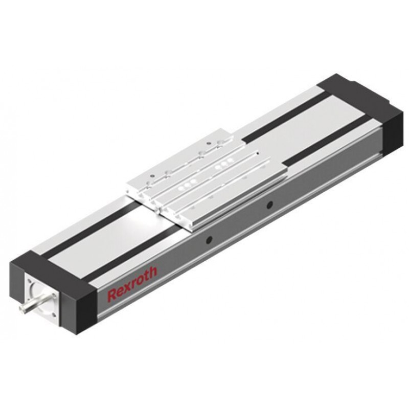
Компактные модули с шариковинтовым приводом CKK-200-NN-1 Bosch Rexroth представляют собой устройства, которые используют для автоматизации различных процессов в промышленности.
Компактные модули CKK-200-NN-1 выполняют следующие задачи:
- точное и плавное перемещение объектов в горизонтальной плоскости. Модули могут использоваться для перемещения различных грузов, оборудования или инструментов;
- регулирование положения объектов в пространстве. Это является важным, когда необходима высокая точность и стабильность положения;
- эти модули CKK-200-NN-1 легко интегрируются в системы автоматизации производства. Их можно совмещать с различными контроллерами и программным обеспечением, тем самым управлять ими с помощью компьютера или другого устройства;
- эти устройства изготавливаются из высококачественных материалов и обладают прочной конструкцией. Они могут выдерживать высокие нагрузки и работать в тяжелых условиях, обеспечивая долгий срок службы.
- данные модули легко установить и настроить. У них простая система обслуживания, что упрощает их эксплуатацию и увеличивает эффективность работы.
Компактные модули с шариковинтовым приводом CKK-200-NN-1 чаще всего используют в автомобильной, машиностроительной, электронной и пищевой промышленностях. Также они применяются в производственных линиях, робототехнике, автоматических складах и других сферах, где требуется точное и надежное перемещение объектов.
Принцип работы компактных модулей CKK-200-NN-1 заключается в использовании шариковинтового механизма. Шариковинтовой привод преобразует вращательное движение винта в линейное перемещение объекта. Винт снабжен шариками, которые перемещаются по специальным канавкам внутри гайки. При вращении винта гайка перемещается вдоль винта, обеспечивая линейное перемещение объекта. Управление модулем осуществляется с помощью контроллера, который управляет вращением винта и регулирует его скорость и положение.
Description
Features
- Screw support for the realization of high speeds on long assembly lengths for CKK-200
Product description
Structure and attachments

| 1) | Motor attachment – flanged type and coupling |
| 2) | Motor attachment – timing belt side drive |
Structural design
1 Ball Screw Assembly with zero-backlash Single Nut
2Drive-side end block
3Carriage with integrated Runner Block
4 Cover plate
5Cover strip made of reinforced PU strip
6 End block
7 Frame
Attachments:
8 Connection plate
9 Magnetic sensor
10 Mounting channel
11 Socket/plug
12 Flange and coupling
13 Belt side drive
14 Motor
Attachments
- Motor attachments with mount and coupling or via timing belt side drive
- Mounting kits for motors according to customer requirements
- Maintenance-free servomotors with selectable brake and mounted feedback
- Magnetic sensors, switch activation without additional switch tag
- Socket and plug
- Aluminum mounting channel for sensors
Motor attachment with flange and coupling
A motor can be attached to all Compact Modules with Ball Screw Assembly by means of a flange and coupling.
The flange serves to fasten the motor to the Compact Module and acts as a closed housing for the coupling.
The motor’s drive torque is transmitted stress-free through the coupling to the Compact Module’s drive shaft.
Our standard couplings compensate for the system’s thermal expansion.
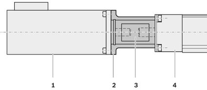
| 1) | Motor |
| 2) | Flanged type |
| 3) | Coupling |
| 4) | Compact module |
Structural design belt side drive
All Compact Modules with Ball Screw Assembly offer the option of attaching the motor via a belt side drive. This makes the overall length shorter than when attaching the motor with flange and coupling. The space-saving, closed pulley housing serves as protection for the belt and as a motor bracket.
In addition, various gear ratios are also available (depending on size):
- i = 1
- i = 1.5
- i = 2
The belt side drive can be mounted in four different directions:
- below, above (RV01 and RV02)
- left, right (RV03 and RV04)
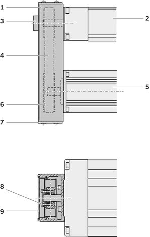
1) Pulley housing made of anodized aluminum frame
2) Compact Module
3) Support bearing on screw journal with size CKK-070
4) Timing belt
5) Motor
6) Timing belt
7) Cover
8) Belt pulleys with tensioning units
9) Cover plate
Design/options for guideway (frame), carriages, connection plates, see section “Dimensions”
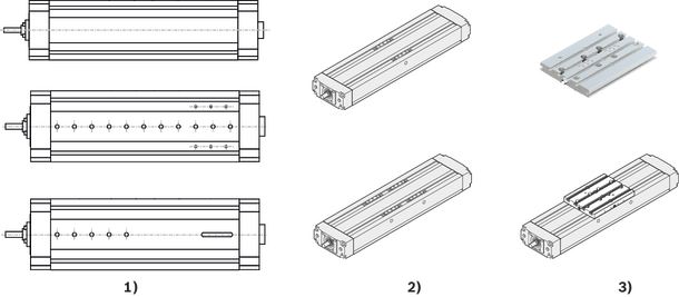
| 1) | Guideway (frame) |
| 2) | Carriages |
| 3) | Connection plates |
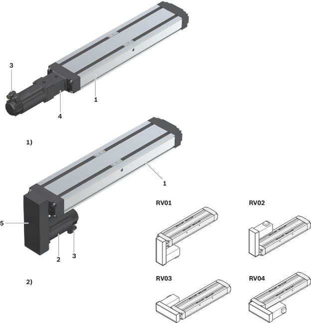
| 1) | Mount and coupling (MF01) |
| 2) | Timing belt side drive (RV01–RV04) |
1 Linear Motion System
2 Motor
3 Motor connector
4 Mount and coupling
5 Timing belt side drive
Lubrication versions
Lube version LSS, LPG
- Grease lubrication with manual grease gun via frame, carriage or via connection plate
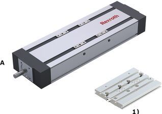
| 1) | Connection plates |
A Drive side
Lube version LCF, LCO
- 3 lube fittings
- Prepared for connection to central lubrication systems
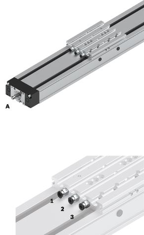
A Drive side
1 Lube connection, Runner Block left
2 Lube connection, Runner Block right
3 Lube connection, Ball Screw Assembly
Notes:
LSS:
- Initial lubrication by Bosch Rexroth
- Relubrication using manual grease gun
LPG:
- Ball Rail System and Ball Screw Assembly only with corrosion prevention
- Relubrication using manual grease gun
- Basic lubrication required
LCF:
- Prepared for connection to central lubrication systems for liquid grease (NLGI grade 00 in accordance with DIN 51818)
- • Lubrication with liquid grease only via single-line piston distributor system
- Basic lubrication required
LCO:
- Prepared for connection to central lubrication systems for oil
- Oil lubrication only via single-line piston distributor system
- Runner Block and Ball Screw Assembly nut with integrated non-return valves
- Basic lubrication required
Screw support for Compact Module CKK-200
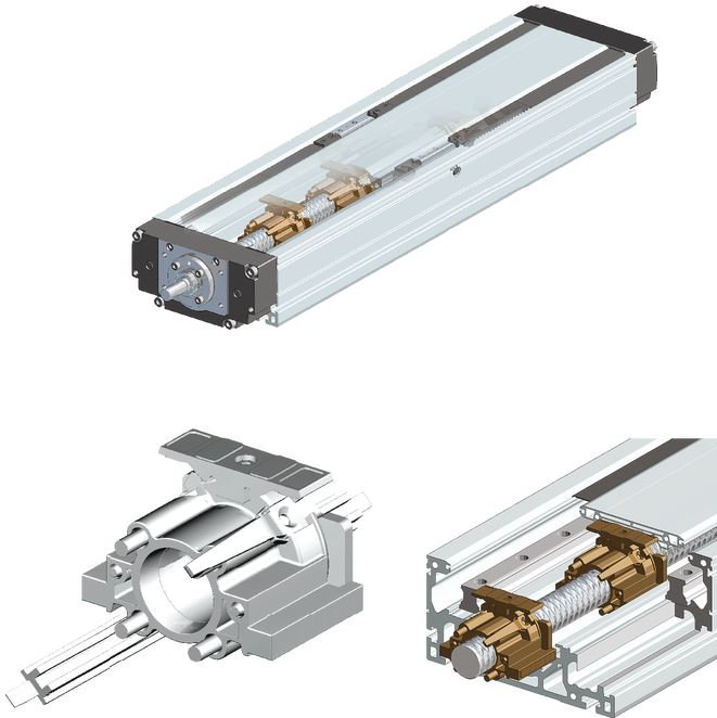
Structural design:
- Guidance of the screw supports in the frame.
Features:
- High speed over longer lengths of up to 5500 mm.
- Elastomer buffer provides cushioning between carriage and screw supports.
- Screw supports are maintenance-free.
- Screw supports are protected by the cover sheet and cover strips.
- The screw supports prevent the cover sheet from sagging in all directions.
Caution: Screw support is designed for horizontal operation only.
“Resist” cover

1) Cover plate
2) Connection plate
3) Sealing profile from FKM
4) Bracket for sealing profile
5) Mounting bracket for cover plate
6) Guideway for sealing profile
7) Toothed sealing profile
8) Connections for central lubrication system (see Chapter "Maintenance”)
Design:
- Sizes: CKK -110, -145, -200
- For versions with connection plate
Characteristics:
- Increased protection through toothed sealing profile
- Perfect integration of the sealing profile is provided by the integrated guideway on the carriage
- Sealing profile made of flexible FKM material
- LABS free (substances impairing the wetting properties)
- Sealing profile interchangeable
- Short-term temperature resistance of the sealing profile up to 300°C
- Suitable for dry chip loading with aluminum chips and handling of components during welding application
- Selectable for all lubrication types
Technical data
Suitable loads
Regarding the desired service life, loads for Fmgw, Fmbsshould not exceed around 20 % of the dynamic characteristic values (Cgw, Cbs).
See Chapter "Project planning notes", document "Calculation".
Do not exceed the technical data for the Linear Motion System.
Note on dynamic load capacities and moments (see the table)
Determination of the dynamic load ratings and moments is based on a total travel of 100,000 m.
Often only 50,000 m are actually stipulated. For comparison: Multiply values C, Mt and ML from the table by 1.26.
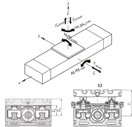
| 1) | Applicable to CKK-110, -145, -200 with Resist cover |
Note: Observe the document "Calculation" in the section "Project planning notes".
Load capacities and moments
|
Size |
CKK-200 | |||||||||||||||||||||||||||||||||||||
|
Lca |
without connection plate 1) |
mm |
79,5 | 254,5 | 255,5 … 429,5 | |||||||||||||||||||||||||||||||||
|
With connection plate 2) |
mm |
190 | 305 | - | ||||||||||||||||||||||||||||||||||
|
LW |
mm |
- | 175 3) | 176 … 350 3) 4) | ||||||||||||||||||||||||||||||||||
|
d0 x P |
mm |
32 x 5 | 32 x 10 | 32 x 20 | 32 x 32 | 32 x 5 | 32 x 10 | 32 x 20 | 32 x 32 | 32 x 5 | 32 x 10 | 32 x 20 | 32 x 32 | |||||||||||||||||||||||||
|
Number SPU |
0 | 1 | 2 | 3 | 0 | 1 | 2 | 3 | 0 | 1 | 2 | 3 | 0 | 1 | 2 | 3 | 0 | 1 | 2 | 3 | 0 | 1 | 2 | 3 | 0 | 1 | 2 | 3 | 0 | 1 | 2 | 3 | 0 | |||||
|
Cgw |
N |
74600 | 121185 | |||||||||||||||||||||||||||||||||||
|
Cbs |
N |
23310 | 34200 | 21240 | 21060 | 23310 | 34200 | 21240 | 21060 | 23310 | 34200 | 21240 | 21060 | |||||||||||||||||||||||||
|
Cfb |
N |
26000 | ||||||||||||||||||||||||||||||||||||
|
Mt |
Nm |
4849 | 7877 | |||||||||||||||||||||||||||||||||||
|
ML |
Nm |
1053 | 10604 | 60,59 x Lw 5) | ||||||||||||||||||||||||||||||||||
|
Mx max |
Nm |
1375 | 2750 | |||||||||||||||||||||||||||||||||||
|
My max |
Nm |
299 | 3701 | 21,14 x Lw 5) | ||||||||||||||||||||||||||||||||||
|
Mz max |
Nm |
299 | 1744 | 9,97 x Lw 5) | ||||||||||||||||||||||||||||||||||
|
Fy max |
N |
12265 | 19925 | |||||||||||||||||||||||||||||||||||
|
Fz1 max |
N |
21150 | 42300 | |||||||||||||||||||||||||||||||||||
|
Fz2 max |
N |
21150 | 42300 | |||||||||||||||||||||||||||||||||||
|
ly |
cm⁴ |
612 | ||||||||||||||||||||||||||||||||||||
|
lz |
cm⁴ |
3008 | ||||||||||||||||||||||||||||||||||||
|
Z1 |
without connection plate |
mm |
36 | |||||||||||||||||||||||||||||||||||
|
With connection plate |
mm |
63 | ||||||||||||||||||||||||||||||||||||
|
with connection plate for cover Resist |
mm |
86.4 | ||||||||||||||||||||||||||||||||||||
| 1) | In the design “without connection plate” the carriage length Lca corresponds to the measurement from the outer edge to the outer edge of the fixing screw. Dynamic parameters and maximum permissible loads are valid only when connecting the fixing screw via customer attachment. |
| 2) | The connection plate is mounted on the carriage design “without connection plate.” For the design with connection plate, the carriage length Lca corresponds to the length of the connection plate. |
| 3) | A variable centerline-to-centerline distance LW is only possible for the carriage design "without connection plate.” The centerline-to-centerline distance between the minimum and maximum distance can be freely chosen in millimeter steps. |
| 4) | Screw support (SPU) is not available for carriage design with centerline-to-centerline distance LW . |
| 5) | For the variable LW, ML, My max and Mz max must be determined according to the selected center-to-center distance LW. |
Note: Observe the document "Calculation" in the section "Project planning notes".
General technical data
|
Size |
CKK-200 | |||||||||||||||||||||||||||||||||||||
|
Lca |
without connection plate 1) |
mm |
79,5 | 254,5 | 255,5 … 429,5 | |||||||||||||||||||||||||||||||||
|
With connection plate 2) |
mm |
190 | 305 | - | ||||||||||||||||||||||||||||||||||
|
LW |
mm |
- | 175 3) | 176 … 350 3) 4) | ||||||||||||||||||||||||||||||||||
|
d0 x P |
mm |
32 x 5 | 32 x 10 | 32 x 20 | 32 x 32 | 32 x 5 | 32 x 10 | 32 x 20 | 32 x 32 | 32 x 5 | 32 x 10 | 32 x 20 | 32 x 32 | |||||||||||||||||||||||||
|
Number SPU |
0 | 1 | 2 | 3 | 0 | 1 | 2 | 3 | 0 | 1 | 2 | 3 | 0 | 1 | 2 | 3 | 0 | 1 | 2 | 3 | 0 | 1 | 2 | 3 | 0 | 1 | 2 | 3 | 0 | 1 | 2 | 3 | 0 | |||||
|
Lad |
without connection plate |
mm |
120.5 | 235.5 | 360.5 | 485.5 | 120.5 | 235.5 | 360.5 | 485.5 | 120.5 | 235.5 | 360.5 | 485.5 | 120.5 | 235.5 | 360.5 | 485.5 | 120.5 | 235.5 | 360.5 | 485.5 | 120.5 | 235.5 | 360.5 | 485.5 | 120.5 | 235.5 | 360.5 | 485.5 | 120.5 | 235.5 | 360.5 | 485.5 | 120.5 | |||
|
With connection plate |
mm |
10 | - | 10 | - | 10 | - | 10 | - | 70 | 185 | 310 | 435 | 70 | 185 | 310 | 435 | 70 | 185 | 310 | 435 | 70 | 185 | 310 | 435 | - | ||||||||||||
|
smin 5) |
mm |
80 | ||||||||||||||||||||||||||||||||||||
|
Lmax |
mm |
2200 | 3500 | 4600 | 5500 | 2200 | 3500 | 4600 | 5500 | 2200 | 3500 | 4600 | 5500 | 2200 | 3500 | 4600 | 5500 | 2200 | 3600 | 4700 | 5500 | 2200 | 3600 | 4700 | 5500 | 2200 | 3600 | 4700 | 5500 | 2200 | 3600 | 4700 | 5500 | 2200 | ||||
|
mca |
without connection plate |
kg |
3.2 | 3.4 | 3.6 | 3.8 | 3.2 | 3.4 | 3.6 | 3.8 | 3.2 | 3.4 | 3.6 | 3.8 | 3.2 | 3.4 | 3.6 | 3.8 | 5.2 | 5.4 | 5.6 | 5.8 | 5.2 | 5.4 | 5.6 | 5.8 | 5.2 | 5.4 | 5.6 | 5.8 | 5.2 | 5.4 | 5.6 | 5.8 | 5.2 | |||
|
With connection plate |
kg |
5.5 | - | 5.5 | - | 5.5 | - | 5.5 | - | 8.9 | 9.1 | 9.3 | 9.5 | 8.9 | 9.1 | 9.3 | 9.5 | 8.9 | 9.1 | 9.3 | 9.5 | 8.9 | 9.1 | 9.3 | 9.5 | - | ||||||||||||
|
kg fix |
kg |
4.06 | ||||||||||||||||||||||||||||||||||||
|
kg var |
kg/mm |
0.0296 | ||||||||||||||||||||||||||||||||||||
| 1) | In the design “without connection plate” the carriage length Lca corresponds to the measurement from the outer edge to the outer edge of the fixing screw. Dynamic parameters and maximum permissible loads are valid only when connecting the fixing screw via customer attachment. |
| 2) | The connection plate is mounted on the carriage design “without connection plate.” For the design with connection plate, the carriage length Lca corresponds to the length of the connection plate. |
| 3) | A variable centerline-to-centerline distance LW is only possible for the carriage design "without connection plate.” The centerline-to-centerline distance between the minimum and maximum distance can be freely chosen in millimeter steps. |
| 4) | Screw support (SPU) is not available for carriage design with centerline-to-centerline distance LW . |
| 5) | Minimum required travel distance to ensure a reliable lubrication distribution. |
Length calculation
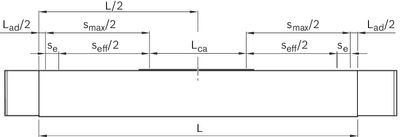

For length calculation values, see the "General Technical Data" table.
Modulus of elasticity E of the Linear Motion System

Effective stroke
Stroke: Maximum distance from carriage center to the outer-most switch activation points.
Excess travel: Excess travel must be greater than braking distance. The acceleration travel can be adopted as the guideline value for the braking distance.
Mass of the Linear Motion System
Weight calculation:
- without motor
- without switch mounting
- without motor attachment

Note: Observe the document "Calculation" in the section "Project planning notes".
Drive data
|
Size |
CKK-200 | |||||||||||||||||||||||||||||||||||||
|
Lca |
without connection plate 1) |
mm |
79,5 | 254,5 | 255,5 … 429,5 | |||||||||||||||||||||||||||||||||
|
With connection plate 2) |
mm |
190 | 305 | - | ||||||||||||||||||||||||||||||||||
|
d0 x P |
mm |
32 x 5 | 32 x 10 | 32 x 20 | 32 x 32 | 32 x 5 | 32 x 10 | 32 x 20 | 32 x 32 | 32 x 5 | 32 x 10 | 32 x 20 | 32 x 32 | |||||||||||||||||||||||||
|
Number SPU |
0 | 1 | 2 | 3 | 0 | 1 | 2 | 3 | 0 | 1 | 2 | 3 | 0 | 1 | 2 | 3 | 0 | 1 | 2 | 3 | 0 | 1 | 2 | 3 | 0 | 1 | 2 | 3 | 0 | 1 | 2 | 3 | 0 | |||||
|
mca |
without connection plate |
kg |
3.2 | 3.4 | 3.6 | 3.8 | 3.2 | 3.4 | 3.6 | 3.8 | 3.2 | 3.4 | 3.6 | 3.8 | 3.2 | 3.4 | 3.6 | 3.8 | 5.2 | 5.4 | 5.6 | 5.8 | 5.2 | 5.4 | 5.6 | 5.8 | 5.2 | 5.4 | 5.6 | 5.8 | 5.2 | 5.4 | 5.6 | 5.8 | 5.2 | |||
|
With connection plate |
kg |
5.5 | - | 5.5 | - | 5.5 | - | 5.5 | - | 8.9 | 9.1 | 9.3 | 9.5 | 8.9 | 9.1 | 9.3 | 9.5 | 8.9 | 9.1 | 9.3 | 9.5 | 8.9 | 9.1 | 9.3 | 9.5 | - | ||||||||||||
|
kJ fix |
without connection plate |
kg·mm² |
71.348 | 71.474 | 71.601 | 71.728 | 76.612 | 77.119 | 77.625 | 78.132 | 93.299 | 95.326 | 97.352 | 99.378 | 127.391 | 132.578 | 137.766 | 142.953 | 72.741 | 72.867 | 72.994 | 73.121 | 82.185 | 82.691 | 83.198 | 83.705 | 115.59 | 117.676 | 119.643 | 121.669 | 184.455 | 189.642 | 194.83 | 200.018 | 72.741 | 82.185 | 115.59 | 184.455 |
|
With connection plate |
kg·mm² |
72.867 | - | 82.691 | - | 117.616 | - | 189.642 | - | 75.147 | 75.274 | 75.4 | 75.527 | 91.81 | 92.317 | 92.823 | 93.33 | 154.092 | 156.118 | 158.145 | 160.171 | 283.02 | 288.207 | 293.395 | 298.583 | - | ||||||||||||
|
kJ var |
kg·mm |
0.605 | 0.64 | 0.639 | 0.617 | 0.605 | 0.64 | 0.639 | 0.617 | - | ||||||||||||||||||||||||||||
|
kJ m |
mm² |
0.633 | 2.533 | 10.132 | 25.938 | 0.633 | 2.533 | 10.132 | 25.938 | - | ||||||||||||||||||||||||||||
|
MRs |
Nm |
1.1 | 1.2 | 1.4 | 1.1 | 1.2 | 1.4 | 1.5 | 1.15 | 1.3 | 1.5 | 1.7 | 1.25 | 1.4 | 1.7 | 1.9 | 1.2 | 1.3 | 1.5 | 1.2 | 1.3 | 1.5 | 1.6 | 1.25 | 1.4 | 1.6 | 1.8 | 1.35 | 1.5 | 1.8 | 2 | 1.2 | 1.25 | 1.35 | ||||
|
amax |
m/s² |
17.9 | 30.7 | 50 | 17.9 | 30.7 | 50 | 17.9 | 30.7 | 50 | ||||||||||||||||||||||||||||
| 1) | In the design “without connection plate” the carriage length Lca corresponds to the measurement from the outer edge to the outer edge of the fixing screw. Dynamic parameters and maximum permissible loads are valid only when connecting the fixing screw via customer attachment. |
| 2) | The connection plate is mounted on the carriage design “without connection plate.” For the design with connection plate, the carriage length Lca corresponds to the length of the connection plate. |
Note: For the max. drive torque Mp and max. speed vmax see section on "Diagrams / Characteristic curves".
Mass moment of inertia of the linear system

Determination of translative mass moment of inertia of the external load

Note: Observe the document "Calculation" in the section "Project planning notes".
Drive data for motor attachment via mount and coupling
|
Size |
Motor |
Coupling |
Mount and coupling |
|
|
McN |
Jc |
mfc |
||
|
Nm |
10‑6 kgm2 |
kg |
||
|
CKK-200 |
MS2N06 |
50 |
210 |
1,80 |
|
MS2N07 |
98 |
390 |
2,25 |
|
Normal operating conditions
|
Size |
CKK-200 | |
|
Permissible ambient temperature with Rexroth servo motor 1) |
0 °C ... +40 °C | |
|
Permissible ambient temperature for mechanical system 2) |
-10 °C ... +60 °C | |
|
smin 3) |
mm |
80 |
| 1) | Performance losses from 40°C |
| 2) | No passing below the dew point |
| 3) | Minimum required travel distance to ensure a reliable lubrication distribution. |
Note: Contamination is not permitted!
Legend
|
Symbol |
Description |
Unit |
|
amax |
Maximum acceleration travel |
m/s2 |
|
BASA |
Ball screw assembly |
- |
|
Bt |
Belt type |
- |
|
Cgw |
Dynamic load capacity, linear guide |
N |
|
Cbs |
Dynamic load capacity, ball screw drive |
N |
|
Cfb |
Dynamic load capacity, fixed bearing |
N |
|
d0 |
Nominal diameter of ball screw drive |
mm |
|
Fmbs |
Dynamic equivalent load on bearing of the Ball Screw Assembly |
N |
|
Fmgw |
Dynamic equivalent load on bearing of the guideway |
N |
|
Fy max |
Maximum dynamic load in y-direction |
N |
|
Fz1 max |
Maximum dynamic load in z-direction |
N |
|
Fz2 max |
Maximum dynamic load in z-direction |
N |
|
i |
Transmission |
- |
|
ly |
Y-axis planar moment of inertia |
cm4 |
|
lz |
Z-axis planar moment of inertia |
cm4 |
|
Jc |
Mass moment of inertia of the coupling |
kgm2 |
|
Js |
Mass moment of inertia of the linear system |
kgm2 |
|
Jsd |
Reduced mass moment of inertia of timing belt side drive on the motor journal |
kgm2 |
|
Jt |
Translatory mass moment of inertia of external load based on the Linear Motion System screw journal |
kgm2 |
|
kg fix |
Constant for fixed portion of the mass |
kg |
|
kg var |
Constant for variable-length portion of the mass |
kg/mm |
|
kJ fix |
Constant for fixed-length portion of mass moment of inertia |
kgmm2 |
|
kJ m |
Constant for mass-specific portion of mass moment of inertia |
mm2 |
|
kJ var |
Constant for variable-length portion of mass moment of inertia |
kgmm |
|
L |
Length of linear motion system |
mm |
|
Lad |
Additional length |
mm |
|
Lca |
Carriage length |
mm |
|
Lmax |
Maximum length |
mm |
|
LW |
Carriage center-to-center distance |
mm |
|
mca |
Moved mass of system of carriage |
kg |
|
McN |
Rated torque of coupling |
Nm |
|
mex |
Moved external mass |
kg |
|
mfc |
Mass of mount and coupling |
kg |
|
ML |
Dynamic longitudinal moment load capacity |
Nm |
|
MRs |
Frictional torque of system |
Nm |
|
MRsd |
Friction moment of belt side drive at motor journal |
Nm |
|
ms |
Mass of the Linear Motion System (without attachments) |
kg |
|
msd |
Mass of belt side drive |
kg |
|
Msd |
Maximum permissible drive torque of the timing belt side drive |
Nm |
|
Mt |
Dynamic torsional moment load capacity |
Nm |
|
Mx max |
Maximum admissible torsional moment around the x-axis |
Nm |
|
My max |
Maximum admissible torsional moment around the y-axis |
Nm |
|
Mz max |
Maximum admissible torsional moment around the z-axis |
Nm |
|
P |
Screw lead |
mm |
|
se |
Excess travel (excess travel se should be greater than braking distance. The acceleration travel can be used as a guideline for braking distance.) |
mm |
|
seff |
Effective stroke |
mm |
|
smax |
Maximum travel range |
mm |
|
smin |
Minimum travel |
mm |
|
Screw support |
Screw support |
- |
|
Z1 |
Application point of the effective force |
mm |
Diagrams/characteristic curves
Permissible drive torque
The values shown for Mp apply under the following conditions:
- Screw journal without keyway
- No radial loads on screw journal
Caution:
Keep in mind the nominal torque of the coupling being used!
Keep in mind the minimum travel distance smin, see Chapter “Technical data”!
Caution:
Screw journal with keyway:
For reasons of stress concentration and the reduction of the effective diameter, adhere to the maximum values for drive torque!
Caution:
For Ball Screw Assemblies with keyway, the smallest value from the diagrams and the table is valid.
|
Size |
Mp |
|
Nm |
|
|
CKK-110, CKK-145 |
no reduction |
|
CKK-200 |
48,6 |
Example of screw journal with keyway
|
CKK-200 |
d0 x P |
||
|
32 x 32 |
32 x 10 |
||
|
Length |
mm |
1500 |
1500 |
|
Mp from diagram |
Nm |
58,5 |
39,0 |
|
Mp max. |
Nm |
48,6 |
48,6 |
|
Value for dimensioning |
Nm |
48,6 |
39,0 |
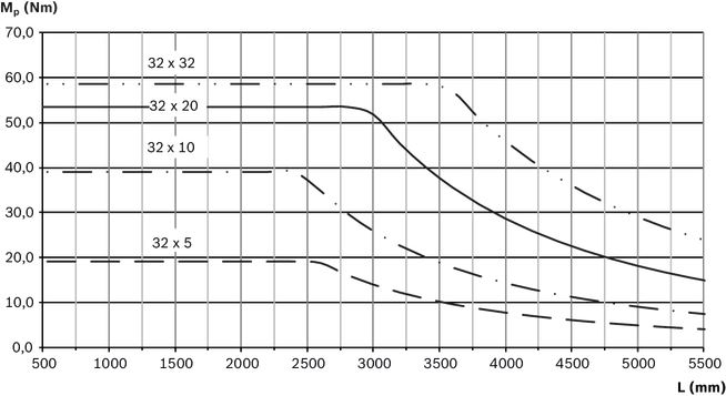
Permissible speed
Observe motor speed!
Observe the minimum travel distance smin, see section “Technical data”!
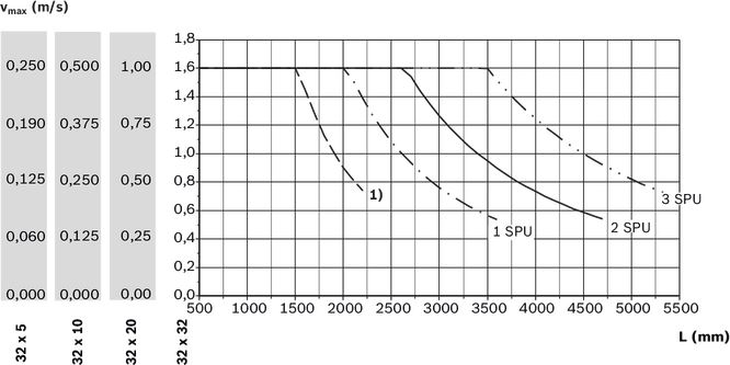
| 1) | without screw support |
Dimensions
Straightness and flatness tolerance in accordance with DIN EN 12020-2.
Notes: All dimensions are given in mm. Drawings not schematically to scale.
Exact contours and dimensions can be found in the CAD model.
For dimensional drawings for motor attachment, see Chapter "Motor attachment".
For the length calculation of the Linear Motion System see Chapters “Technical data” and “Project planning notes”, document “Calculation”.
Frame dimension drawings

| 1) | Lubrication bore on both sides (grease lubrication). For more information, see section “Maintenance” |
| 2) | deep |
| 3) | Version |
|
TT |
Carriage |
Dimensions
|
Size |
CKK-200 | ||
|
b |
P9 |
mm |
5 |
|
⌀d |
h7 |
mm |
16 |
|
⌀D1 |
mm |
68 | |
|
Tolerance for ⌀D1 |
mm |
- 0.01 | |
|
⌀D2 |
mm |
32 | |
|
h |
mm |
3 | |
|
H3 |
mm |
56 | |
|
K1 |
M8 | ||
|
K2 |
mm |
12 | |
|
K3 |
mm |
46 | |
|
K4 |
mm |
90 | |
|
K5 |
mm |
112 | |
|
K6 |
mm |
85.5 | |
|
L1 |
mm |
35 | |
|
L2 |
mm |
47.5 | |
|
L3 |
mm |
59.5 | |
|
L4 |
mm |
28 | |
|
L5 |
mm |
3.5 | |
|
L7 |
mm |
14 | |
|
L8 |
mm |
58 | |
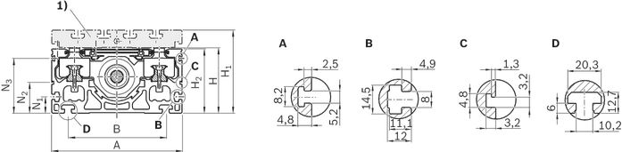
| 1) | For connection plate, see section “Accessories” |
|
A |
For switch mounting arrangements |
|
B |
For mounting with clamping fixtures |
|
C |
For mounting duct |
|
D |
For fastening with sliding blocks |
Dimensions
|
Size |
CKK-200 | |
|
A |
mm |
200 |
|
B |
mm |
150 |
|
H |
mm |
100 |
|
H1 |
mm |
127 |
|
H2 |
mm |
98.5 |
|
N1 |
mm |
25 |
|
N2 |
mm |
47.5 |
|
N3 |
mm |
84 |
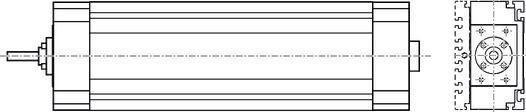
Option 01 / standard
View from below (ground area)
Option 03 / with central holes
View from below (ground area)
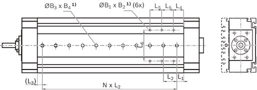
| 1) | deep |
Dimensions, option 03
|
Size |
CKK-200 | ||
|
B1 |
M8 | ||
|
B2 |
mm |
12 | |
|
⌀B3 |
H7 |
mm |
16 |
|
B4 |
mm |
3.1 | |
|
L1 |
mm |
20 | |
|
L2 |
mm |
40 | |
|
Tolerance for L2 |
mm |
± 0.01 | |
|
L3 |
min |
mm |
10 |
|
L4 |
mm |
35 | |
|
L5 |
mm |
40 | |
|
L6 |
mm |
119 | |
Option 04 / with central holes and long hole
View from below (ground area)
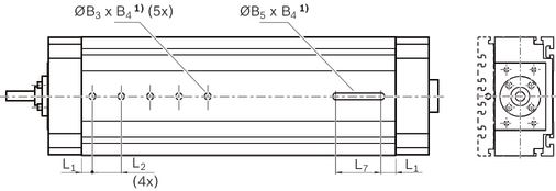
| 1) | deep |
Dimensions, option 04
|
Size |
CKK-200 | ||
|
ØB3 |
H7 |
mm |
16 |
|
B4 |
mm |
3.1 | |
|
B5 |
H8 |
mm |
16 |
|
L1 |
mm |
20 | |
|
L2 |
mm |
40 | |
|
Tolerance for L2 |
± 0.01 mm | ||
|
L7 |
mm |
60 | |
Carriage dimension drawings
Carriage without connection plate
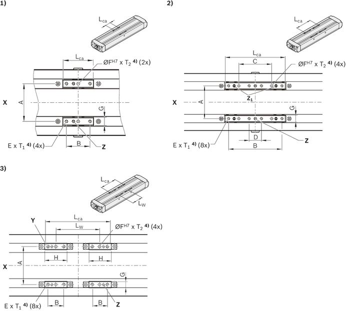
| 1) | Fig. 1 |
| 2) | Fig. 2 |
| 3) | Fig. 3 |
| 4) | deep |
|
X |
Drive side |
|
Y |
Driving runner block |
|
Z/Z1 |
Lubrication option for grease; closed with set screw. |
Dimensions
|
Size |
CKK-200 | ||||
|
Picture |
1 | 3 | |||
|
Lca 1) |
mm |
79,5 | 254,5 | 255,5 … 429,5 | |
|
LW |
mm |
- | 175 2) | 176 … 350 2) 3) | |
|
A |
mm |
130 | |||
|
B |
mm |
60 | |||
|
E |
M8 | ||||
|
⌀F |
H7 |
mm |
8 | ||
|
G |
mm |
16 | |||
|
H |
mm |
79.5 | |||
|
T1 |
mm |
16 | |||
|
T2 |
mm |
12 | |||
| 1) | In the design “without connection plate” the carriage length Lca corresponds to the measurement from the outer edge to the outer edge of the fixing screw. Dynamic parameters and maximum permissible loads are valid only when connecting the fixing screw via customer attachment. |
| 2) | A variable centerline-to-centerline distance LW is only possible for the carriage design "without connection plate.” The centerline-to-centerline distance between the minimum and maximum distance can be freely chosen in millimeter steps. |
| 3) | Screw support (SPU) is not available for carriage design with centerline-to-centerline distance LW . |
Carriage with connection plate
Dimension diagrams, see section “Accessories,” connection plates
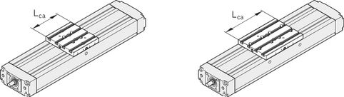
Resist cover

Dimensions
|
Size |
A |
B2 |
C |
H |
H11 |
H12 |
H13 |
Lca |
Z11) |
|
mm |
mm |
mm |
mm |
mm |
mm |
mm |
mm |
mm |
|
|
CKK-200 |
200 |
212 |
27 |
100 |
150 |
82 |
24 |
305 |
86,4 |
| 1) | Z1 = application point of the effective force |
Legend
|
Symbol |
Description |
Unit |
|
L |
Length of linear motion system |
mm |
|
Lad |
Additional length |
mm |
|
Lca |
Carriage length |
mm |
|
LW |
Center-to-center distance between carriages |
mm |
|
se |
Excess travel (excess travel se should be greater than braking distance. The acceleration travel can be used as a guideline for braking distance.) |
mm |
|
seff |
Effective stroke |
mm |
|
smax |
Maximum travel range |
mm |
Project planning information
Mounting
Caution! Do not secure or support the Compact Module at the end enclosures! The frame is the load-bearing part!
Mounting with clamping fixtures
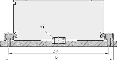
| 1) | For Compact Modules with centering holes in the ground area (selection via the guideway option): Use centering rings to better align to other Linear Motion Systems and connection elements. |
|
Size |
A |
B |
|
mm |
mm |
|
|
070 |
82 |
95 |
|
090 |
102 |
112 |
|
110 |
126 |
140 |
|
145 |
161 |
175 |
|
200 |
222 |
240 |
Mounting with sliding blocks

| 1) | For Compact Modules with centering holes in the ground area (selection via the guideway option): Use centering rings to better align to other Linear Motion Systems and connection elements. |
Mounting by means of special modification in the base surface of the frame is possible
Guideway option 03 already includes threaded holes in the ground area of the frame (see dimension drawings).
Special modification in the base surface of the frame
(not available from factory)
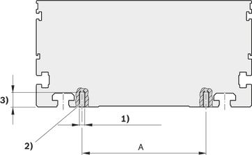
| 1) | Pin hole or thread max. ØB |
| 2) | Distance from frame ends at least 30 mm |
| 3) | Max. C |
|
Size |
A |
B |
C |
|
mm |
mm |
mm |
|
|
070 |
59 |
3 |
7,5 |
|
090 |
76 |
4 |
7,5 |
|
110 |
92 |
5 |
9,0 |
|
145 |
124 |
6 |
13,0 |
|
200 |
119 |
8 |
12,0 |
Magnetic sensor with free cable end
1 Socket and plug
2 Sensor
3 Mounting duct
Alternatively, the sensor can also be attached by switch mounting plate and cable holder.
See the magnetic sensor with plug.

| 1) | Set screw for retention |
| 2) | Active surface |
Additional component/actuation
A mounting duct is needed to fasten the sensors and cable guides. This is suspended at the side in a slot at the Compact Module and secured with set screws (4).
The set screws are included.
The sensors are pushed into the upper T-slot (CKK/CKR-090,-110 and CKK-145) or into the lower T-slot (CKR-145, CKK/CKR-200) of the mounting duct and secured with set screws.
Switch activation is done by magnets in the carriage.

Magnetic sensor with plug
1 Sensor
2 Switch mounting plate including set screws (loose) and square nut 2a
3 Cable holder including set screw (loose)

Attachment/Actuation
A switch mounting plate (2) is required to attach the sensors. This is suspended in the upper slot on the Compact Module and secured with set screws (4).
The sensors are pushed into the respective slot on the switch mounting plate and secured with one set screw.
The square nut with set screw (2a) serves as a fixed stop for the sensor (switching position when changing sensors). Parts are included in the scope of delivery of the sensor mounting kit.
Switch activation is done by magnets in the carriage.

Overview
Inductive sensors and mechanical switches for CKK/CKR-200
1 Socket and plug
2 Mechanical switch (with attachments)
3 Inductive sensor (with attachments)
4 Switching cam (attachment only at the connection plate)
5 Cable duct
Alternatively, the connection line of the switches can also be attached by cable holder.

Attachment/actuation
The switches are suspended in the upper slot on the Compact Module and secured with set screws (6).
The actuation is done using switching cams (4). This is attached with the screws to the connection plate. Fastening screws are included.

Cable duct
- The additional component is done in the lateral slots of the frame. Fastening screws widen the profile and give the cable duct a secure hold.
The cable duct will accommodate up to two cables for mechanical switches and three cables for proximity switches.
Fastening screws are included.
Socket - plug
Notes:
Socket and plug are not wired.
This allows optimal assignment of switching positions during start-up.
One plug is included.
The plug can be installed in three directions.
For further information, see the "Socket - plug” view.
CKK/CKR-200

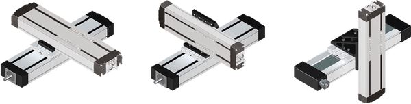
Compact Modules fit together perfectly – fast and flexible
Minimal mounting times, maximum efficiency:
Standardized interfaces significantly reduce the effort during mounting.
The mechanical systems have positive-locking interfaces throughout.
They can be quickly and accurately connected together without time-consuming alignment.
The result:
Users can respond flexibly to handling the different applications and tasks.
For more information about connection technology, see Connection technology for Linear Motion Systems and linear axes.
Connection technology for Linear Motion Systems
Commissioning
Parameterization (start-up)
The nameplate contains reference information on the production of the linear motion system as well as technical start-up parameters.
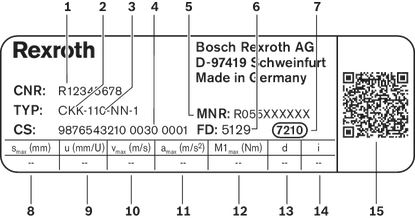
Legend
|
Position |
Symbol |
Description |
Unit |
|
1 |
CNR |
Customer's part number |
- |
|
2 |
TYP |
Short product name |
- |
|
3 |
110 |
Frame size |
- |
|
4 |
CS |
Customer information |
- |
|
5 |
MNR |
Part number |
- |
|
6 |
FD |
Date of production |
- |
|
7 |
7210 |
Manufacturing location |
- |
|
8 |
smax |
Maximum travel range |
mm |
|
9 |
u |
Lead constant without motor attachment |
mm/U |
|
10 |
vmax |
Maximum speed |
m/s |
|
11 |
amax |
Maximum acceleration travel |
m/s2 |
|
12 |
M1max |
Maximum drive torque on the motor journal |
Nm |
|
13 |
d |
Direction of motor rotation to move in positive (+) direction 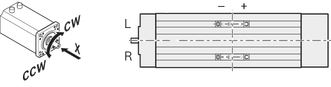 |
- |
|
14 |
i |
Transmission ratio |
- |
|
15 |
- |
QR code |
- |
Maintenance
Accessories
Combination examples

| 1) | End of range (‒) |
| 2) | Reference |
| 3) | End of range (+) |
| 4) | Sensors with plug |
| 5) | Sensors with free cable end |
| 6) | Plug |
| 7) | Sensor extensions |
| 8) | Performance specification: suitable for flexing installation, torsion-resistant, weld spark-resistant |
| 9) | Plug |
| 10) | Adapter |
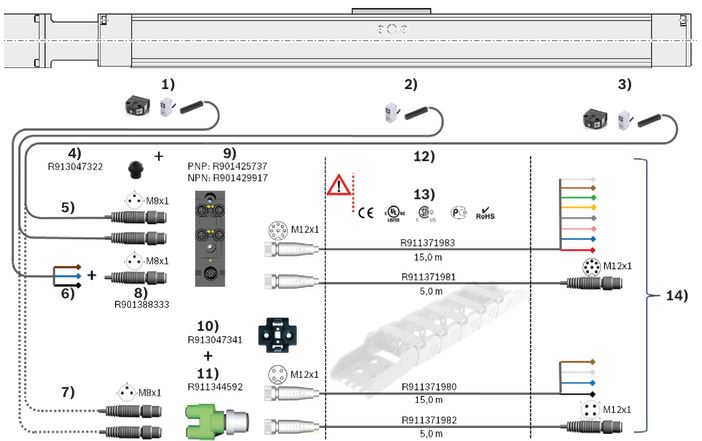
| 1) | End of range (‒) |
| 2) | Reference |
| 3) | End of range (+) |
| 4) | Screw plug |
| 5) | Sensors with plug |
| 6) | Sensors with free cable end |
| 7) | Sensors with plug |
| 8) | Plug |
| 9) | Passive distributor |
| 10) | Holding plate |
| 11) | Passive distributor |
| 12) | Extensions for passive distributors |
| 13) | Performance specification: suitable for flexing installation, torsion-resistant, weld spark-resistant |
| 14) | Higher-level control system |
Clamping fixtures for Compact Modules
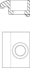
Clamping fixtures for Compact Modules
Sliding blocks and springs for Compact Modules
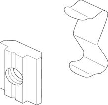
Sliding blocks and springs for Compact Modules
Strips for Compact Modules
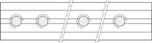
Strips for Compact Modules
Centering rings for Compact Modules

Centering rings for Compact Modules
Covers for Compact Modules

Covers for Compact Modules
Connection plates for CKK 090 … 200, R0375...15
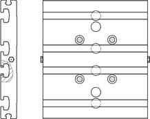
Connection plates for CKK 090 … 200, R0375...15
Connection plates for CKK 090 … 200, R0375...10

Connection plates for CKK 090 … 200, R0375...10
Magnetic sensor with free line end

Magnetic sensor with free line end
Magnetic sensor with M8x1 plug
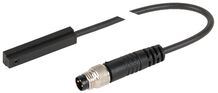
Magnetic sensor with M8x1 plug
Proximity sensor with free line end
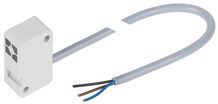
Proximity sensor with free line end
Proximity sensor with M8x1 plug
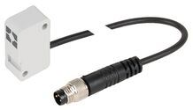
Proximity sensor with M8x1 plug
Additional components for inductive sensor
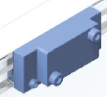
Additional components for inductive sensor
Mechanical switch
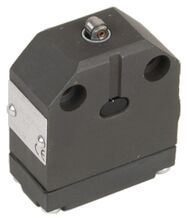
Mechanical switch
Mechanical switch with M8x1 plug
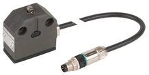
Mechanical switch with M8x1 plug
Additional components for mechanical switch

Additional components for mechanical switch
Extension pieces - assembled on one side

Extension pieces - assembled on one side
Extension pieces - assembled on two sides

Extension pieces - assembled on two sides
Plug-in connector
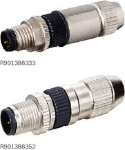
Plug-in connector
Adapter
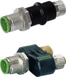
Adapter
Passive distributors
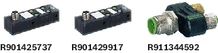
Passive distributors
Holding clip

Holding clip
Plug screw

Plug screw
Extension pieces

Extension pieces
Socket and plug
R037540000
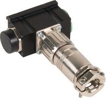
Socket and plug
R037540000
Socket and plug
R117500153

Socket and plug
R117500153
Mounting duct

Mounting duct
Switching angle
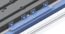
Switching angle
Switch mounting plate
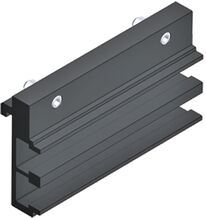
Switch mounting plate
Cable holder
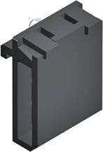
Cable holder
Nozzle pipe
R3455 031 06

Nozzle pipe
R3455 031 06
- For manual grease guns
- For the lubrication of funnel-type and ball-type lube nipples
Frequency meter
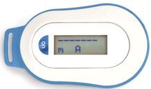
Frequency meter
Delivery notes
Safety Instructions
Motor attachment
Measurement and test reports
Downloads
 |
Declaration of Incorporation for single axis Linear Motion Systems Certificate | R320103141 | 2020-06-01 | All languages | PDF | 409k Product Groups: Linear axes and electromechanical cylinders |
|
Safety Instructions for Linear Motion Systems Manual | R320103152_en | 2015-01-01 | English | PDF | 593k Product Groups: Linear axes and electromechanical cylinders |
|
Compact Modules CKK, CKR Catalog | R999000499 | 2022-02-01 | English | PDF | 24.8MB Product Groups: Compact Modules Compact Modules CKK, CKR |

Нет отзывов об этом товаре.