
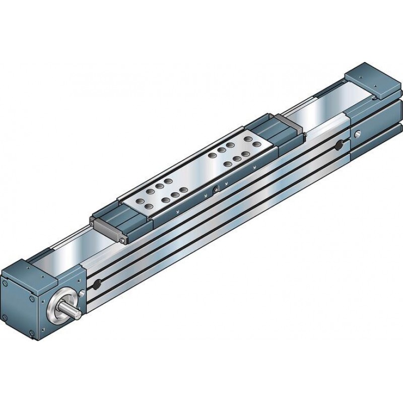
Доступно к заказу
Цена по запросу
И выбери подходящего.
Description
Product description
Structure and attachments
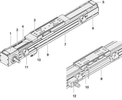
Structural design
1 End head (drive side)
2 Toothed belt (covered)
3 Carriage with runner block
4 Sealing strip for MKR-040/-065/-080/-110/-140
5 Strip fixing for MKR-040/-065/-080/-110/-140
6 End head (clamping side)
7 Main body
Attachments
8 Cable channel
9 Switch bracket
10 Proximity switch
11 Mechanical switch
12 Socket/plug
13 Magnetic field sensor
Models
 | 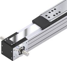 |  |
| Journal for motor attachment right or left | Journal for motor attachment on both sides | With gear reducer (motor mounting via clamping hub) |
Technical data
General technical instructions
Note on dynamic load capacities and load moments
Determination of the dynamic load capacities and load moments is based on a travel life of 100 000 m. Often only 50 000 m is actually stipulated.
For comparison:
Multiply values C, Mt and ML from the table by 1.26.
Suitable loads
Regarding the desired nominal life, in general loads for Fcomb, Fm up to around 20 % of the dynamic characteristic values (C, Mt, ML) have generally proven suitable.
See the "Calculation" document in the "Project planning instructions" chapter for the respective Linear Module.
Do not exceed the technical data for the Linear Motion System.

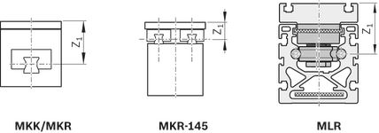
Application point of the effective force (Z1)
Modulus of elasticity E of the Linear Motion System

General technical instructions
Length calculation of the Linear Motion System


For length calculation values, see the "General Technical Data" table.
Note: Adhere to the section "General technical instructions" and the document "Calculation" in the chapter "Project planning instructions".
Load capacities and moments
| Size | MKR-165 | |
| Number of carriages | 1 | |
| Lca | mm | 400 |
| C | N | 84100 |
| Mt | Nm | 1800 |
| ML | Nm | 5130 |
| Mx max | Nm | 720 |
| My max | Nm | 2130 |
| Mz max | Nm | 2130 |
| Fy max | N | 34100 |
| Fz1 max | N | 34100 |
| Fz2 max | N | 34100 |
| Z1 | mm | 123 |
| ly | cm⁴ | 2574 |
| lz | cm⁴ | 3527 |
General technical data
| Size | MKR-165 | |
| Number of carriages | 1 | |
| Lca | mm | 400 |
| smin 1) | mm | 80 |
| Lmax | mm | 12000 |
| mca | kg | 11.5 |
| Repeatability (up to ...) | mm | ± 0.05 |
| 1) | Minimum required travel to ensure a reliable lubrication distribution! If this cannot be achieved, please consult Bosch Rexroth. |
General Technical Data dependent on design / gear unit
| Size | Design / gear unit | kg fix | kg var | Lad |
| kg | kg/mm | mm | ||
| MKR-165 | OA01 | 29,5 | 0,0384 | 40 |
| MA01 – MA03 | 29,5 | |||
| MG01, MG02 (i = 8) | 36,0 | |||
| MG01, MG02 (i = 12, i = 16) | 36,0 |
Note: Adhere to the section "General technical instructions" and the document "Calculation" in the chapter "Project planning instructions".
Getriebedaten
| Size | Gear type1) | i | Mge2) | MRge | nge2) | Jge | mge | Motor |
| Nm | Nm | rpm | kgm2 | kg | ||||
| MKR-165 | PG160 | 8 | 720 | 1,2 | 6500 | 0,0004630 | 18,0 | MSK076C |
| 123) | 1280 | 2,1 | 0,0012400 | 22,0 | ||||
| 163) | 2,2 | 0,0007500 |
| 1) | Planetary gearbox |
| 2) | The limits of the linear motion system must not be exceeded. For more information about calculations, see the chapter "Project planning instructions". |
| 3) | Two-stage gear |
Note: Adhere to the section "General technical instructions" and the document "Calculation" in the chapter "Project planning instructions".
Drive data
| Size | i | Mp | u | vmax |
| Lca | kJ fix | kJ var | kJ m | MRs | d3 | Bt | Fbp4) | Ft zul5) | cspe | amax |
| Nm | mm/U | m/s | mm | kgmm2 | kgmm | mm2 | Nm | mm | N | N | N | m/s2 | ||||
| MKR-165 | 11) | 367 | 440,0 | 5 |
| 400 | 70428 | 7,06 | 4904 | 14,5 | 140,05 | 75AT20 | 5250 | 18000 | 4,2 x 10⁶ | 50 |
| 13) | 200 | |||||||||||||||
| 82) | 45 | 55,0 | 4 |  | 400 | 72485 | ||||||||||
| 122) | 30 | 36,7 | 3 | |||||||||||||
| 162) | 23 | 27,5 | 2 |
| 1) | Valid for versions: 1 or 2 drive journals |
| 2) | Valid for versions: clamping hub or clamping hub with 2nd journal |
| 3) | Version with keyway |
| 4) | Maximum power that can be transmitted through the engaging teeth that are in the belt pulley. |
| 5) | The maximum permissible tensile load on the belt cross section (belt elasticity limit) is given here for easier comparability. This value represents the load limit in terms of plastic deformation and may not be used to calculate the maximum permissible drive torque. |
Normal operating conditions
| Size | MKR-165 | |
| Permissible ambient temperature with Rexroth servo motor 1) | 0 °C ... +40 °C | |
| Permissible ambient temperature for mechanical system 2) | -10 °C ... +60 °C | |
| smin 3) | mm | 80 |
| 1) | Performance losses from 40°C |
| 2) | No passing below the dew point |
| 3) | Minimum required travel to ensure a reliable lubrication distribution! If this cannot be achieved, please consult Bosch Rexroth. |
Note: Application of dirt is not permitted!
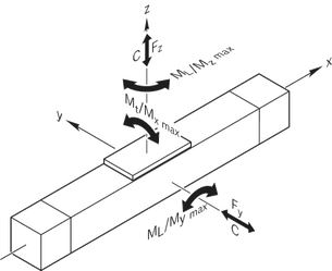
Maximum values for each size
| Size | MKR-165 | |
| C | N | 84100 |
| Mt | Nm | 1800 |
| Mx max | Nm | 720 |
| My max | Nm | 2130 |
| Mz max | Nm | 2130 |
| Fy max | N | 34100 |
| Fz1 max | N | 34100 |
| Fz2 max | N | 34100 |
| Lmax | mm | 12000 |
Legend
| Symbol | Description | Unit |
| amax | Maximum acceleration travel | m/s2 |
| Bt | Belt type | - |
| C | Dynamic load capacity, linear guide | N |
| cspe | Specific spring rate | N |
| D | Motor shaft diameter | mm |
| d3 | Diameter, belt pulley | mm |
| dge | Clamping hub diameter | mm |
| Fbp | Maximum belt drive transmission force | N |
| Ft zul | Belt elasticity limit | N |
| Fy max | Maximum dynamic load in y-direction | N |
| Fz1 max | Maximum dynamic load in z-direction | N |
| Fz2 max | Maximum dynamic load in z-direction | N |
| i | Gear ratio of the gear | - |
| kg fix | Constant for fixed portion of the mass | kg |
| kg var | Constant for variable-length portion of the mass | kg/mm |
| kJ fix | Constant for fixed-length portion of mass moment of inertia | kgmm2 |
| kJ m | Constant for mass-specific portion of mass moment of inertia | mm2 |
| kJ var | Constant for variable-length portion of mass moment of inertia | kgmm |
| L | Length | mm |
| Lad | Additional length | mm |
| Lca | Carriage length | mm |
| Lmax | Maximum length | mm |
| Lw | Carriage center-to-center distance | mm |
| ly | Y-axis planar moment of inertia | cm4 |
| lz | Z-axis planar moment of inertia | cm4 |
| mca | Moved mass of system (carriage) | kg |
| mge | Mass of the gear | kg |
| Mge | Maximum permissible acceleration torque of the gear (on the output drive) | Nm |
| ML | Dynamic longitudinal moment load capacity | Nm |
| Mp | Maximum permissible drive torque of the linear system | Nm |
| MRge | Frictional torque of the gear on the motor journal | Nm |
| MRs | Frictional torque of the system | Nm |
| Mt | Dynamic torsional moment load capacity | Nm |
| Mx max | Maximum admissible torsional moment around the x-axis | Nm |
| My max | Maximum admissible torsional moment around the y-axis | Nm |
| Mz max | Maximum admissible torsional moment around the z-axis | Nm |
| nge | Maximum permissible speed of the gear | rpm |
| se | Excess travel | mm |
| seff | Effective travel distance | mm |
| smax | Maximum travel range | mm |
| smin | Minimum travel | mm |
| u | Lead constant | mm/U |
| vmax | Maximum permissible speed | m/s |
| Z1 | Application point of the effective force | mm |
Diagrams/characteristic curves
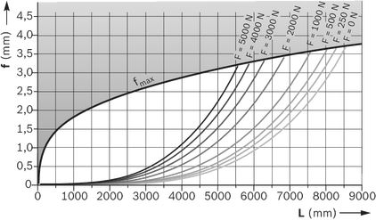
Deflection
Take note of the "General Technical Instructions" part of the "Technical Data" section.
Example
MKR-080 Linear Module: L = 3000 mm, F = 1000 N
from diagram MKR-080: f = 1.55 mm, fmax = 3.75 mm
The deflection f lies well below the maximum permissible deflection fmax, so no additional supports are required.
The following diagram is valid for:
- fixed clamping (200 to 250 mm per side)
- 6 to 8 screws per side
- pay attention to fixed substructure
- Lmax; See Table "General technical data" in the section "Technical data"
Dimensions
All dimensions in mm. Drawings not to scale.
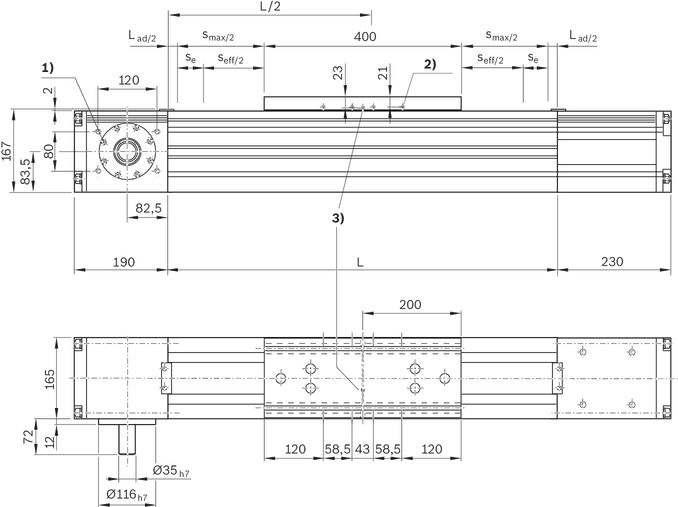
| 1) | M12 - 20 deep (4x) |
| 2) | M4 - 8 deep (4x per side) |
| 3) | Central lubrication (grease lubrication): at any one of the three funnel-type lube nipples DIN 3405-AM6 |
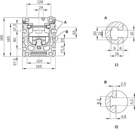
| 1) | For DIN 508-M8 and DIN 557-M10 nut |
| 2) | For cable duct |
Project planning information
Calculation example MKR with gear reducer
Calculation
Mounting
Mounting
General information
The linear modules are mounted using various fastening elements:
- Clamping fixtures
- Sliding blocks for size -110 and up
- Square nuts
- Spring nuts
- Screws for T-slots as per DIN 787 (no picture).
Length depends on base.
When mounting Linear Modules, please note the maximum tightening torques listed in the table.
Tightening torques of fastening screws
with friction factor 0.125 strength class 8.8
 | 8.8 | M4 | M5 | M6 | M8 | M10 | M12 |
 | (Nm) | 2,7 | 5,5 | 9,5 | 23 | 46 | 80 |
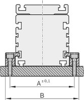
Mounting with clamping fixtures
Mounting with sliding blocks
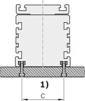
| 1) | 85 (size .. -110) 120 (size -165) |
| Size | A | B | C |
| (mm) | (mm) | (mm) | |
| -040 | 52,2 | 65,5 | - |
| -065 | 81,0 | 95,0 | - |
| -080 | 96,0 | 110,0 | - |
| -110 | 132,0 | 150,0 | 85,0 |
| -140 | 170,0 | 196,0 | 105,0 |
| -145 | 172,0 | 198,0 | 78,0 |
| -165 | 192,0 | 218,0 | 120,0 |
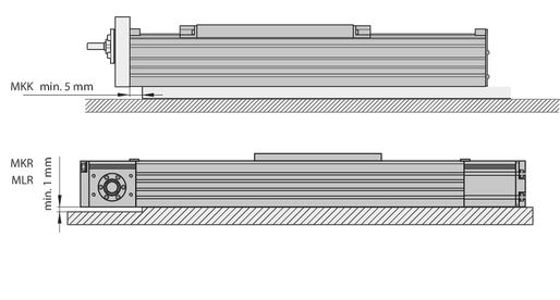
Do not support the linear module on end enclosures, end blocks or on end plates!
The frame is the load-bearing part!
Overview of the switching system
1 Socket and plug
2 Mechanical switch with attachments
3 Proximity switch
4 Switch bracket
5 Mounting channel / cable channel
6 Magnetic field sensor with fixed potted cable
(Reed/Hall sensor (for mounting channel))
7 Reed/Hall sensor with plug and sensor holder
7a: Magnetic sensor
7b: Sensor holder incl. set screws (loose) and square nut
7c: Cable holder (3 pcs) incl. set screw (loose)
7d: M8x1 plug (3-pin)
8 Magnetic switch with M8x1 plug
9 Clamping screw
10 Sliding block
Switch mounting MKK/MKR/MLR-xxx-NN-x
MKK/MKR/MLR-xxx-NN-x
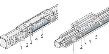
Proximity sensors, mechanical switches and accessories (MKK/MKR/MLR)
Mounting instructions:
The mechanical switches, the proximity sensors and the socket with plug and cable channel are fastened with attachments in T-grooves of the main body. Switch activation is carried out by a switch bracket on the carriage.

| Position | Name | Size -065/-080/-140 /-145-NN-3 | -110-NN-3 | -165-NN-2 |
| Material number | ||||
| 1 | Socket-plug | R117500153 | ||
| 2 | Mechanical switch | see accessories | ||
| Mechanical switch with attachments | R117500151 | |||
| 3 | Proximity sensor | see accessories | ||
| - Attachment parts without sensor | R117500152 | R117520152 | R117500152 | |
| 4 | Switching angle | R117500149 | R117500150 | |
| 5 | Cable duct | R039662017 | ||
| These switching versions can only be ordered with these material numbers. |
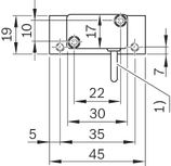
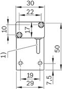
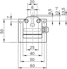
| Proximity sensor with additional attachment for | Proximity sensor with additional attachment for | Mechanical switch with attachment for |
 |  |  |
| 1) | Cable length: 3 m |
Socket and plug, cable duct
Attach the socket to the side with the most switches. The socket and plug are not pre-wired. The variable sliding attachment allows switching positions to be optimized during start-up. The plug can be mounted in three directions.
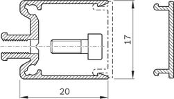
Cable duct
The cable duct is fastened in the T-slots on the side of the frame. Fastening screws widen the profile and ensure that the cable duct is securely mounted.
See the illustration for the position of the slot.
The cable duct will accommodate up to two cables for mechanical switches and three cables for proximity switches.
Fastening screws and cable grommets are included.
Mounting examples of switches
Determination of the switching position
Switching distance: The switching distance is the distance between the carriage center (TM) and the zero point (0) when a switch is actuated (indicated in mm). Example of a mechanical limit switch (assuming the zero point is at L/2):
Maximum switching distance = 0.5 x (max. travel distance) – excess travel = 0.5 x effective stroke
For safe operation of the linear module the excess travel must be greater than the braking path.
For MKR... and MLR...: The acceleration travel sa can be assumed as the reference value for the braking distance.
For MKK...: In most cases, the following is sufficient as a guideline value for the excess travel (braking path): Excess travel = 2 x screw lead P.
Note the smallest possible switching distance (determined by attachments):
mechanical-mechanical = 60 mm; mechanical-proximity = 45 mm; proximity-proximity = 28 mm.
for MKR-145: mechanical-mechanical = 62 mm; mechanical-proximity = 49 mm; proximity-proximity = 35 mm
The switches as well as socket with plug are fixed in the upper T-slots of the frame and actuated by a switch tab on the carriage.
Mounting side of the switches:
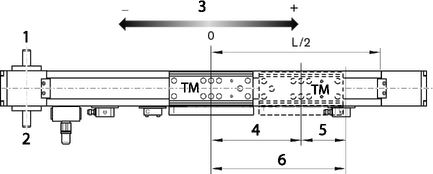
| 1) | links (L) |
| 2) | right (R) |
| 3) | Direction of travel |
| 4) | 0.5 x stroke |
| 5) | Excess travel |
| 6) | 0.5 x max. travel path |

Commissioning
Parameterization (start-up)
The nameplate contains reference information on the production of the linear motion system as well as technical start-up parameters.
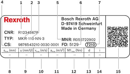
| Position | Symbol | Description |
| 1 | CNR | Customer's part number |
| 2 | TYP | Short product name |
| 3 | 110 | Size |
| 4 | CS | Customer information |
| 5 | MNR | Part number |
| 6 | FD | Manufacturing date |
| 7 | 7210 | Manufacturing location |
| 8 | smax | Maximum travel range |
| 9 | u | Lead constant without motor attachment |
| 10 | vmax | Maximum speed |
| 11 | amax | Maximum acceleration travel |
| 12 | M1max | Maximum drive torque at motor journal |
| 13 | d | Direction of motor rotation to move in positive (+) direction CW = clockwise CCW = counter clockwise 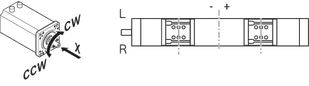 |
| 14 | i | Gear ratio |
| 15 | QR code |
Maintenance
Lubrication
Delivery notes
Form of delivery
Product generation 2:
Linear Modules with a ball screw drive or belt drive are delivered fully assembled.
Motor attachment - motor:
If a combination of motor mounting and motor has been chosen, the attachment of the components is done as shown in the figure below. When ordering Linear Modules only with a motor mounting (without motor!), not all parts can be mounted. Final assembly must then be carried out by the customer. All necessary instructions and parameters for professional assembly are included.
The installation version is selected and determined during product configuration, and it is a part of the order key.
MKR with clamping hub (MA05, MA06)
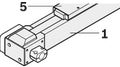
MKR with planetary gearbox (MG...)

1 Linear module
2 Motor
3 Mount and coupling
4 Timing belt side drive
5 Carriage
6 Motor connector
7 Gearing
Motor connector position
An individually selectable motor connector position is not configurable for product generation 2 linear modules, therefore a standard position is specified upon delivery. For motor connector location, see "Order details" chapter, "Configuration and ordering" document.
Switching system
Cable duct, switch, switching cam and socket with plugs are included as loose parts.
Lubrication
Product generation 2 Linear Modules are delivered with initial greasing.
For information on lubricants, see the "Maintenance" chapter.
Documentation
Each Linear Module is supplied together with the appropriate documentation upon delivery.
Safety Instructions
Required and supplementary documentation
For further instructions and information, please refer to the documentation for this product.
You can find PDF files of these documents on the Internet at www.boschrexroth.com/mediadirectory.
We would also be happy to send you the documents that you want.
If you are unsure about using this product, please contact Bosch Rexroth.
Motor attachment
All dimensions in mm. Drawings not to scale.
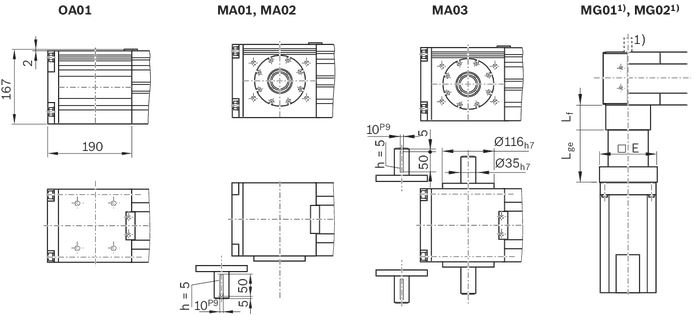
| 1) | For drive option 31: second journal Ø35 x 72 mm |
Abmessungen
| Motor coding | ▢ E | Lf | Lge | ||
| i = 8 | i = 12 | i = 161) | |||
| mm | mm | mm | mm | mm | |
| MS2N07-B1BNN | 140 | 96 | 168,5 | 218 | 218 |
| MS2N07-C1BRN | |||||
| MS2N07-D1BNN | |||||
| 1) | Two-stage gear |
Measurement and test reports
load errorDownloads
 | Declaration of Incorporation for single axis Linear Motion Systems Certificate | R320103141 | 2020-06-01 | All languages | PDF | 409k Product Groups: Linear axes and electromechanical cylinders |
| Safety Instructions for Linear Motion Systems Manual | R320103152_en | 2015-01-01 | English | PDF | 593k Product Groups: Linear axes and electromechanical cylinders |
| Linear Modules MKK / MKR / MLR Catalog | R999000496 | 2021-03-01 | English | PDF | 17.5MB Product Groups: Linear Modules |

Нет отзывов об этом товаре.